Saturday, 20 October 2012

Neuron Decomposition

Final Animation:
There are lots of things which I learnt throughout development of this Animation, which I will update later. For now, below is the final Animation:


This is the WIP of an animation which is based on harmful impact of  radiation coming from devices such as mobile phones /base-stations on Human Body. It is a well - known fact that our body has it's own bio-field and it gets disrupted due to extensive use of devices which radiates energy.

The idea was to represent the effect on the most vital organs, thus I selected "Neurons" because of their contribution in our daily work.
Modeling,Simulation and Rendering is done in Maya with V-ray as Render-engine. 
Texturing is done in Mari for Foreground Neurons and those in the back have procedural textures.
A rough composite for this shot is done in Adobe Photoshop.


Below is a snapshot of the WIP:


Textures Used:

Procedural Texture Samp:


Unwrapped UV'd Texture:


Wireframe Sample: 


Linear Wokrflow in Mari:

Following is the process adopted by me for creating all textures in linear color-space:


 Simulation Playblast:


Saturday, 25 August 2012

Blending Fluids

Blend in between two fluids done in Autodesk 3Ds Max,KCM,Krakatoa,Frost,RealFLow. Everything is rendered in VRay and COmposited in Nuke.


The main motive behind this animation was to learn KCM in 3Ds Max and have a basic understanding of Vertex based color mapping, besides this following were the artists which inspired me to create this animation:
Carlos Grury Santos
Yuval Kolton

UV and Textures:

Textures are Unwrapped in 3DS MAx and are painted in Adobe Photoshop.
juiceBoxDiffuse
box_Unwrap


juiceBoxSpec


leaf_Unwrap


spec


diffuse_front
sub_Surf


bump


The Process:

First of all we need two fluids from any fluid simulation Application, I used Real Flow with a very basic set-up.
The important thing however, is to make sure that following channels are exported so that they can be referenced and manipulated later, channels are:
Age,
Lifespan(optional),
Velocity(optional),
Vorticity(optional),
Everything is optional except age, (hehe) as we will use "AGE" channel and tell 3Ds max to start blending or changing the color of particle stream after some specified value( which we will decide later) is reached.

Ok , now in max we will use Krakatoa Magma Flow to read channels.

I did a bit of research regarding "how to" process a bit and found following resources quite useful:
http://www.thinkboxsoftware.com/frost-data-channel-interpolat/
http://www.thinkboxsoftware.com/frost-meshing-modes/
http://www.thinkboxsoftware.com/frost-combining-frost-and-krak/

http://forums.thinkboxsoftware.com/viewtopic.php?f=89&t=6177

Following steps are what I used to create the animation, but certainly they aren't the only way of doing a fluid blend, as krakatoa with KCM and Frost are quite powerful for any creative solution.
One can find some useful tips and tricks of how to use Krakatoa,KCM and Frost together on THinkBox website:


Step1:
 I loaded particle streams in their respective Krakatoa's Prt Loaders.
       Think box Frost was used to mesh out these particles and frost's mesh-output was used  to render the scene, and using more than one Prt-Loader for particle stream inside Frost was giving artifacts.
So, the idea was to use a single PrtLoader for meshing but the question that popped up was how to distinguish two particle streams inside a single PrtLoader?

                                                                                   
Figure1
Here is the snapshot of assigning manual Material IDs for one of the two particle streams so they can be distinguished later when used, with a single PrtLoader inside Frost for Meshing.(with an Integer with some value that matches the material ID in the material editor).
                                 
I used Age input and connected it to "MXSFloat" , without which I was getting the following error.                                                                                                           

Figure2


Figure3


Lastly, all channels shown in the figure3 were written out by using Partitioning inside Krakatoa.


Step2:
    I loaded the particle stream written out in a new PrtLoader and used the MtlIndex as my input channel to distinguish particle streams(as shown in Fig4).
The output of the Figure 4 will be used in the Blend material by Vertex colour map to blend material color values where these particles streams will come in contact to each other.
Figure4


One can change the MXSFloat Channel back in to the Age channel or same can be used in the process.


I changed it back to Age with int32 data Type.


Step3:
 Now to Blend these particles into a new color or new material, I used Age as the input channel and normalized it with the value shown in Figure 5.

The normalized output is a checked against each particle's age in the particle stream depending on whether they are equal or less than the normalized value, they will have an output of  0 or 1 which is used in the Second input or the Green Channel.

Figure 5
As shown in the Figure 5 the output MXSInteger from Step2 is used in the Vector Node's first input or Red Channel after being converted to a Float value.

Now the output of this vector node is written out one of  the Mapping channels provided by KCM( in my case it's Mapping channel 5).


Material Configuration:

Red color channel of Mapping Channel 5 output is used by the vertex map in the third slot of the Blend Material (figure 6) to interpolate in between the two float values 0 and 1 for the two particle streams. This will try to interpolate between the colors of two materials in the Blend material slot.
Figure 6


The interpolated values will be touch darker as they will be in between 0 and 1.


Figure 7


Finally to convert this intermediate blend into the final material , I used a second Blend Material (Figure7) which had the Blend material from the Previous step in the first slot and a third material in the second slot. Selection between the first and second material is done on the basis of the Green Channel values (decided by the Normalized Age output) of the Mapping Channel 5.


Finally I added the PrtLoader in the Frost and meshed it out with the final Blend material Assigned to the Frost. In order to see the Blend in the viewport one has to turn on the Vertex Channel Display  with  Vertex Colour  selected from the drop Down and  Shaded  button pressed for the Object Properties of the Frost Mesh.
Here are the out puts in the viewport:

Particle Blend:


Frost_Blend:


More on Fluid blend using frost and Krakatoa can be found in the Forum shown Below:


http://forums.thinkboxsoftware.com/viewforum.php?f=89


bump

Thursday, 5 July 2012

Maya Fluids

Ohk , the Final Render. Detail description about my process will follow shortly.


BreakDown:


Introduction:


While learning Maya Fluids I thought of creating a shot with explosion in it. This shot helped me to explore more about basic Fluid Container parameters and how they can be varied for specific needs, although there are things which I still do not understand :)

Final Simulation Time for all elements: 18 hours
Total Rendering Time: 10 hours
Post /Compositing: 5 hours

Investment of time to Explore is a Must:
 Maya Fluid Container has numerous parameters which are inter-dependent and this makes it hard
to notice the impact of a change made. To avoid confusion, it is  must to experiment,explore with small simulations and explore them first before they can be implemented in the major shot.

There were some Hardware constraints while simulating the explosion, so I was extra-cautious in making most of the MegaHertz on the Machine I have.
Here is the specification of the machine:

Video Card Specs:(Click on to view it in Original Size)


Computer Specs:


To explore more about Maya Fluids I found following resources quite helpful:

Cg-Talk Forums:

    http://forums.cgsociety.org/showthread.php?f=86&t=741591&page=1&pp=15
    http://forums.cgsociety.org/showthread.php?f=86&t=757114&page=1&pp=15
    http://forums.cgsociety.org/showthread.php?t=933045
    http://forums.cgsociety.org/showthread.php?f=86&t=859380

Duncan's Corner:
    http://area.autodesk.com/blogs/duncan/

David Schoneveld:
    https://vimeo.com/agentfx

Soup:

http://soup-dev.websitetoolbox.com/
This is an interesting website to search for new plug-ins or addons not only for the Maya Fluid but for the entire Maya Software in general. I will try the "Uprez" Fluid utility once my new computer will finish rendering.

Intial Thoughts:
With my computer specifications in mind and being new to the Maya Fluids, I decided to separate
Explosion shots in to different elements so to experiment and learn more through different set-ups.

Following are the shot elements:
Main Explosion
Major ShockWave
Ground Dust
Debris Smoke Trails

Major issue with the Maya Fluid is that when cached it cannot be re-timed to slow down the motion of the Fluid. This is because of the non-linear relationship in between the Input parameter like Density with the output Parameter Opacity. Simple and thorough explanation for the same can be found here:

http://forums.cgsociety.org/archive/index.php/t-884414.html


Following are the ways I found to slow down the Fluid Motion:

1 Keying down simulation rate- This is not good for lengthy simulations as it causes unexpected fluid            Behaviour.

2 Playing back entire simulation at less speed- This will change the intial shape alogwith the motion.

3 The third and the most effective way which I tried but didn't used is the one given by Eric Cloutier.
He describes about his method on the following link:-

http://forums.cgsociety.org/showthread.php?t=927014

he is retiming fluid simulation for slow motion scene requirements while mantaining the shape of
the fluid. This method produces a very smooth fluid scaled down in motion as can be seen here:
http://www.youtube.com/watch?v=YjSoEE59kOo

This didn't worked for me as the cache created by this method was never loaded on my poor computer with only 1.2 Gb of RAM.

Simulation Set-Up:
Fields:
It is important to include fields initially in the Fluid Simulation as fields are applied to voxels with higher density, therefore if one adds fields later after simulating the fluid then results may be unexpected.

Field for Main Explosion:
For Main Explosion I used a Volume Axis field which was key-framed to give that extra push to the fluids.

This is it's set-up for the Main Explosion(around and along axis have a value of 0.5 each):

   1. No Impact on the Fluid as shown by dotted arrows:


2  Pushing Fluid towards Camera for few frames:


3. Moving Fluid Upwards and a bit of circular motion around the axis shown by the thin line-spacing:


Fields for Shock-Wave:

Volume-Axis Field-

I used  Volume Axis Field with Sphere Shape which had -ve Y direction, was away from center and around axis with some positive values.This set up again made fluid to push away from center and at the same time
making it swirl around the center.

Turbulence Field-
I used Turbulence Field with Higher frequency to add more smaller and detail noise to the Fluid look
besides that high phase values made it change quite often within frames.

Fluid Containers:
Container For Main Explosion:
Resolution and size for this Fluid container was 80,90,90, as the system started crashing above this resolution for my simulation. I wished to had more height at same X and Z scale values but failed to achieve so.
The Boundary was set to -ve Y with X and Z set to None.
All grids are set to Dynamic except Fuel as I am not emitting Fuel in to the Fluid.


Dynamic Simulation:
All Default except :
Damp was set to 0.001, didn't keyed it, controlled fast moving fluid through bouyancy parameter of each Fluid Grid. This was easier and gave better results than the other way around.

High Detail Solve was set to All grids except Velocity, as this keeps the simulation more stable while having drastic swirl values for longer run.

Simulation Rate scale of  3.0.

Content Detail parameters:

All Parameters are set to default except:

Buoyancy of temperature and density being keyed to control and hold Fluid motion with
no Dissipation and Diffusion.

Temperature turbulence with a value of 5 was used to create some randomness in hot regions(regions with
more temperature Grid values) which were shaded out by using Incandescence ramp.

Velcoity Swirl was set to 10 .

Shading Parameters:
 Edge Dropoff  was keyed to avoid the obvious cube shape of the Fluid touching container's boundaries.


Set up for the ramps can be seen from the snapshot.
It's important to know that this incandescence ramp will be visible for the fluid where it has extreme temperature grid values. The dark side of the incandescence ramp  will give a way to the color ramp to shade out the fluid.

Moreover, it is the Color ramp which interacts with light , leading to shadows and other effects.
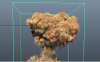


There is slightly brighter color value on the incandescence ramp on the extreme left which gets added to the color ramp to lit those high turbulent and relatively hot temperature grid values in the fluid. As can be seen this adds contrast to the fluid by separating darker and lighter regions.

In order to avoid a sharp falloff one can use a darker color value on the extreme left of the incandescence ramp next to the brighter value. This will result in a nice and smoother blend among ramp color values.

Texturing:


Settings for the texturing can be found on the right,
I avoided using animated texture origin and texture time as the
fluid was moving faster enough for the texture motion to be noticed. Besides this,coordinate method was set to grid which was sufficient enough to provide different texture values for all voxels.


Lighting:
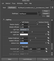


I  rendered the entire cached Fluid simulation on the other machine with Maya 2011 installed.
As Maya 2011 has option to add ambience to the fluid this can be use to fake effects like multi-scattering or adding atmosphere to the fluid.


Configuration for shock wave's container is almost same as the one for the main explosion with few tweaks here and there.

Issues:
 I re-timed the fluid  cache in Maya 2011 with a new Time node, however while doing a batch render the render output was showing the same frame.

Along with this there was an issue with the Debris Smoke Trails which I did using Maya-Particle system.
These were different in the Batch render from what I'd in the simulation in the view-port.


I found a workaround for this by rendering out each pass separately using "Preview animation" feature inside Option tab when Mental Ray is selected as the renderer.
Preview Animation will render exactly the same animation as seen in the viewport and save it inside the "temp" folder of the current project directory.


Debris Smoke Trail:
To shade particles with cloud type I used Dave's video tutorial on Vimeo as a reference.


https://vimeo.com/5429867

Post/Compositing:
 Post work was done in Nuke by adding camera shake, glow and compositing all Fluid elements together.

Camera Dust Particles :


Here is a small update on the explosion WIP.


This is a low resolution video.
I will add debris and dust to complete this. After rendering the explosion I just got to know that there are few  nice additions in context to lighting fluids under Lighting category inside Maya 2011, so I might re-render it for better results.


Hi,

I am starting this thread to post of some of my learning experience with Maya Fluids.
Thanks for all information available regarding Maya Fluids all over CgTalk, which had made it slightly easier for beginners like me to learn Fluids in Maya.

To start with here is a small PlayBlast of Explosion and a Fire WIP, I did in Maya 2010, will post up the details once I am done with the Texturing, Rendering and Compositing.


A Fire WIP:

Friday, 20 April 2012

RANDOM STUFF:


                                                         00.A bit of Scripting
Hi,

While I am rendering an animation on one of my computers, I thought it's a right time to update one of my scripts from last year. The rendering is still in progress and as usual rendering fluids is quite pain-full (taking 2-3 hours for a frame). The link for few screen-shots of what I am rendering can be found on CG TANTRA forum:
http://www.cgtantra.com/forums/showthread.php?p=213055#post213055

The script, changes the path of the directory for all or for some specific "Texture File Nodes", and is useful in situation where someone wants to change the Directory/folder from where the Images will be read by Autodesk Maya during project.
Although, the script which I wrote could had been written in a more robust way with tailor made High_Level_Languages like Pyqt/Python, however I wanted to know the DAG structure inside Maya -mainly how it can be traversed-,and since my knowledge of Python is a bit limited, so I chose to wrote this script in  MEL which I personally found more like C++/C.

Link for downloading the script:

http://www.creativecrash.com/maya/downloads/scripts-plugins/data-management/c/directory-path-change-script

Here are some of it's features:
 Enables one to:

       * Update path of the textures/image files for all file nodes in the scene.
       * Update  path of the textures/image files for specific files (e.g. files named using some naming convention like spec_XYZ,axv_SPEC001 etc.)

Limitations:
   * While updating specific files in the scene, user has to make sure that the file naming conventions are such that  the string which one wants to search among the file-names should have the occurrence of it's first character  before it's duplicate entry .

For example:-
     Searching for file with the file-name "scene01_Spec01.tga" with search keyword "spec" won't be found by the script as character "s" occurs before the "Spec" word. In contrast to this, the same keyword search will give a match if the file convention is like spec01_scene0.tga.

   *Moreover the search is case sensitive.


Here are some screenshots:

Option1:


Option2:


To conclude I learnt DAG in MAYA to some extent and it did help me refreshing my knowledge of programming.  I made this for my personal project during Masters', one can use this script on their own risk. In case you guys have any ideas or suggestion regarding the script, you can reach me at my email address: shashi.woolverine@gmail.com.


Tuesday, 21 February 2012

Fracturing -A fringe Title Test

Hi,
   This is a shot which I did to practice a bit more with PFlow in Autodesk 3Ds Max:


A brief  Shot Description:


 This shot which I decided to experiment with is inspired from one of my favourite and famous american TV show named-"Fringe".

 A small link to the original shot is mentioned below-
                                                 
     http://www.youtube.com/watch?v=fM1bzVVrgNk


Since, being a series involving Investigations around mysteries, all these Title shots encompass every small detail which a typical Science-Fiction show would require. In my opinion, this shot which involves fracturing of a text "FRINGE"  has some indirect connotations about the show itself which are noted down by me:

1. Integration of Debris in to a single element :- points towards  an approach where conclusion is made after going through every small relevant detail.

2.Addition of smoke, Fingerprints and spotlight in the background :- connotes to the mystery being looked closely , especially related to some crime.

3 Lighting and Position of the Text :- emphasize on the "FRINGE" text which is being the centre of attraction which is  supported by the compositional value of the Text itself.

OHK! well there is something about the saturated Blue colour giving it a cold look and besides that the camera movement also plays an important role, any ways here are details about my procedure:-

Shot Requirements and Tools used-


* Particle-flow in Autodesk 3Ds  Max for Fracture Simulation for Particles.
*A fracturing script by "Martin Breidt" from ScriptSpot a link is mentioned below:
http://www.scriptspot.com/3ds-max/scripts/mbfracture

*A Particle Flow script to assign geometry shapes to the particles by Bobo- I will be adding a snapshot of the script later and a script written by me which triggers fracturing from right to left.

*A basic Spotlight rig to lit the scene and Foundary Nuke to composite the entire shot

A  Description:


Simulation


Pflow Set-up:-
                 To start with I used Martin Briedt  fracturing script which has quite nice functions to detect whether the geometry to be fractured has any open faces or isolated vertices which can cause issues while fracturing.
Besides this the script allows one to have a more control over the subdivision of polygons causing smooth faces of the fractured objects.


An event flow window's snapshot:


To give a specific motion to fractured elements instead of using Reactor/Phsyx I decided to go with the Pflow. So, initially I took Bobo's script to assign these fractured geometric shapes to my particles. The script has a check condition where the assignment of shapes, indexes and age of the particles are set before the frame 0. A small snapshot of the script:-


Next Step was to  trigger fracture motion from right to left for this I wrote a small script  which checks the number of particles inside an event and send them to the next event where the Forces take over the control of the entire motion. Since being new to scripting in the Pflow initially, I made a mistake of not using indexing to check the particle inside an event which resulted in computer crashes due to infinite loop :(


Self_Analysis:


"Well when I realized what was going on with the scene my computer had crashed numerous of occasions, and I figured out that 3Ds Max implicitly passes an integer with value 1 to the particles which are checked for some condition inside the script. So, when a particle with index 1 is passed to the next event Max will still look for the particle with index 1 in the same event and if this is executed inside a loop it will result in a CRASH  :-x"


Here is a small snapshot of my script:


Finally in the Fracture simulation I used a Particle Float number to control the influence of forces  on the particles. This requires a two step process, in which first of all the Force operator is required to be told about the use of the script float value this is known as Script wiring and can be initialized as shown in the snapshot-


In the script on has to flag on the use of the  "ParticleFloat channel",
here is a small snapshot where I am controlling the influence of forces like gravity on the particles depending on their respective sizes.


For more information on the script wiring and other stuff please check the link below:
 http://docs.autodesk.com/3DSMAX/14/ENU/MAXScript%20Help%202012/


A Simulation PlayBlast:-


A Rough Comp Test:


The smoke is prepared by using Pflow driven FumeFx simulation a small glimpse of the animation is
shown below:

Test sim:

Final sim:


The simulation is rendered with Vray, with a very basic material having a cellular bump on it.


Compositing:

             The Background with fingerprints and dust marks in the original  shot, is moving along with the camera. Instead of rendering it out I used a 2d solution where the background is fixed at it's position however scratches and finger prints are moving on top of the 2D background.

The spotlight effect is done by using a roto paint mask which is used to over blow the Background image and is animated from left to right.

A nuke tree for compositing:-


To conclude:
  I had a hard time while lighting these fractured Objects due to the sliced faces  which under normal light set-up were giving over exposed regions with value greater than 1.0, so I used the event based lighting by adding events in to specific spotlights and excluding rest.

I still feel that I should have done a bit better with the colour,lights and the end transition where it stops suddenly.


Tuesday, 7 February 2012

Dry Ice Aka Crawling some effect

Hi,

Last week I was wondering whether one can use Pflow<->FumeFx<->Krakatoa for organic effects like smoke. Although FumeFx provides rendering and simulation of most of the effects however for a specific need one can not underestimate the potential of scripting in PFlow and faster rendering capabilities of krakatoa.

I have a machine with 6Gb of RAM and i7 950 processor, well while rendering the simulation -of 97 million particles- the simulation, laughed at my system configuration. Okay so here is my method to create a crawling smoke like effect.

Pflow:-
  In order to create this effect I needed a system where particles can be generated from a source in such a way so that they spread out with some varying speed and posses random position along their path.

Gravity force is used to pull down the generated particles in the first event and once  particles were generated a deflector is used to collide my particles against with. The collided particles were tested and were send to the next event where I'd wind taking over the motion of the particles by applying turbulence as an effect. There are three wind fields with spherical shapes in order to spread the effect of the wind in a spherical gradient.

In order to limit particles along the surface a script test was used to delete any particle that moves above a certain height. Particles with high speed are passed on to the next event where a vortex is applied to give a motion to the particles at high speed. Once again any particles that was moving above a certain height along Z-axis is deleted.

Pflow_Hierarchy:


An expression to avoid particles moving up:


Fume-FX:-
All of the parameters inside FumeFx were configured in such a way so that it follows the basic sim from Pflow. I started with turning down Gravity to 0.1 and Smoke Buoyancy to -10. The value of turbulence was  kept relatively low(0.5), and velocity damping came handy in controlling the speed of the simulation which was set to 0.01. The scale of the turbulence was set to 5.0 and the phase of the turbulence was changing after every 20 frames. This was responsible for the swirling smoke type behaviour, lastly the simulation was done with Spacing equal to 1.0 and the resolution of he entire simulation was:450x450x200.
The final cached simulation was somewhere around 112GB which was too much on a 500 Gb disk which i have, but fortunately I was able to manage that.

A small glimpse of the fume sim:


Krakatoa PrtFumeFx Emitter: 
ThinkBox Krakatoa allows a voxel based simulation rendering from a simulation engine like FumeFx by providing a PrtFumeFx emitter. This emitter can be used to further subdivide fumeFx voxel based particles in to smaller subgroups however in my case since the simulation was having over half a million particles it was impossible for me to do so. Besides this, one can partition particles by using krakatoa to increase particle numbers. PrtFumeFx object can replace Voxels retrieved from the FumeFx into particles besides this one can use the "Align FumeFx source with the PrtFumeFx emitter which makes particles moves in the same manner as they were simulated in FumFx.

Particles were shaded by using Krakatoa Channel Manager by normalizing velocities of particles.
A small video clip of the render which this time I rendered at a very low resolution because of the limited resources can be seen below:


More on partitioning and PrtFumeFX can be found here:


About PrtFumeFx emittter:
http://www.thinkboxsoftware.com/krak-prt-fumefx/

About Rendering with FumeFx simulation with PRTFumeFx emitter:
http://www.thinkboxsoftware.com/krak-fumefx-direct-rendering/

Last but not the least I realised that my machine(6Gb RAM) cannot handle anything above 90 million particles.
So here is what I concluded out of this simulation:
While rendering a simulation containing 94,030,240 million particles, with a partitioned particle file size of over 1.8Gb( for a frame), krakatoa does a fairly good job and renders it out in 4:08 seconds which however demands a Ram of 5.11 Gb.
Krakatoa inside  Autodesk 3Ds Max was not able to reallocate the memory to render more particles due to some reason which is still not clear to me. I consider it because of the 6Gb limited Ram capacity, which isn't enough to swap the cached files containing huge amount of paticles.


Wednesday, 18 January 2012

Smoke Tail


Smoke Tail:


A smoke Tail Test combining Krakatoa and FumeFx. There are about 3 million particles in this small shot and this is straight out of the 3DsMax.
For colour, I 'd Normalized Velocity of the particles while using a gradient map using the Explicit mapping channel mode.


Tuesday, 3 January 2012

Walkman Morphing

Hi Everyone,

This animation is an experiment to look in to the possibilities of "Vertex Colour Shading" feature provided by ThinkboX Frost and KCM. I have used Real Flow to prepare a simulation of a paint splash which gets transformed in to a Sony's Walkman logo, the simulation has some issues with the particle drops bursting up in  the space.
Anyway, following section will explain my process of creating this animation:


Real Flow Simulation:
I made use of Real Flow Container to subdivide my particles inside Real-flow  which made me break down the flow and this allowed me to have more control over my particles throughout the scene. This was achieved by making use of Filters inside the Real Flow. Following are the parameters for the fluid:


Resolution:-3.0
Density:-5000.0 (This is an important parameter as I used this to control Vertex shading of my Fluid)
Viscosity:-7.0  (Increasing this  parameter above or equal to 10 caused inter-particle collisions leading to              abnormal fluid behaviour)
Surface Tension:-50.0

The SIM:


(Hmm the simulation is missing the big spherical dot which is done separately and then loaded into the scene by using Krakatoa PRT Loader.)
The simulation is done by using Magic Daemon in Real Flow.

Using  Frost to Mesh Particles:


Step 1-Loading Real Flow bin files into Autodesk 3DS Max2012 by using Krakatoa's Prt Loader.


Step 2-Using KCM for creating a Mapping channel:


I used the Magma Flow editor to normalize the density of my particles, so that the values lies in the range of 0 to 1. This was used as a value to colour out mesh later while shading the mesh created in Frost.


Step 3- Using Frost to create a Mesh:


To mesh the particles was a bit difficult job as the animation itself contains fluid moving up against the gravity. As I wanted the mesh to have a paint splash effect, I used following settings in order to achieve the results, one can take this further by tweaking parameters mentioned below:

Meshing: Zhu/Bridson

Zhu/Bridson parameters:
Blend Radius:4.5


Particle Size: 0.2


Meshing Quality:
set to Relative to Max. Radius with values:
Render:10.0    (tranforms the mesh at rendering time making it more smoother by subdivision)
Viewport:1.0

A good mesh is always a best values given by Zhu/Bridson's Blend Radius and Particle Size.

Here is the mesh result:


Step 4:- Shader Creation
I made use of the Mapping Channel 2 created in Magma Flow to shade the mesh. The material is a common Vray Material with Gradient map applied to its Diffuse and Refraction parameters, both of which are using Mapping Channel 2. The mapping channel contains values ranging from 0 to 1 as retrieved from the Step 2, hence the areas which are less denser will show light orange colour and will have refraction prominent.

Following is the screen shot of the Material  used by me:-


base material                                     refraction map                                  diffuse map

Step 5:-Rendering
    Render is a 1920X1080 image which is using :

Three Point lighting rig, all of which are area lights ( which cost me heavy rendering time, since I later knew that for area lights shadows, reflection,refraction etc are calculated per light based :(   )

Adaptive DMC as Image sampler
    - which is the best adaptive Image sampler for rendering animation
    -since this sampler uses the average of the sample values collected for a pixel hence unlike it's counterpart  "Adaptive Subdivision" it doesn't require all of  subdivisions/samples to store inside the memory making it  memory efficient.

Indirect Lighting:
Irradiance Map  was the best choice for the primary bounce sampler(GI SAMPLER ALGO) among all other samplers as it provides different presets which automatically configures this sampler.
Beside this one can check the Show Samples  to confirm if there are enough samples for the scene.

I used Brute force  as my secondary bounce sampler.

Suggested reading :


Vertex blending thread:
http://forums.thinkboxsoftware.com/viewtopic.php?f=89&t=4932

About Vray 2.0:
http://www.spot3d.com/vray/help/200R1/index.htm

Here is my Animation, as this is my first time rendering with Vray and Frost C&C are most welcome:


Ohk the most important part of the entire animation is The Rendering TIme which took around 2days and 4 hours :( , which is insanely high, or might be appearing too high to me.